Shroom is interactive lamp installation which is in the same time a sound controller. The idea for this installation comes from Ctrl+Alt controllers, which have become a recognizable trend in new media and game design in recent years. Shroom was made as a project in the Physical Computing class in the New Media program in the Aalto University by Olga Tasanko and Marija Šumarac.
The project was created in three phases:
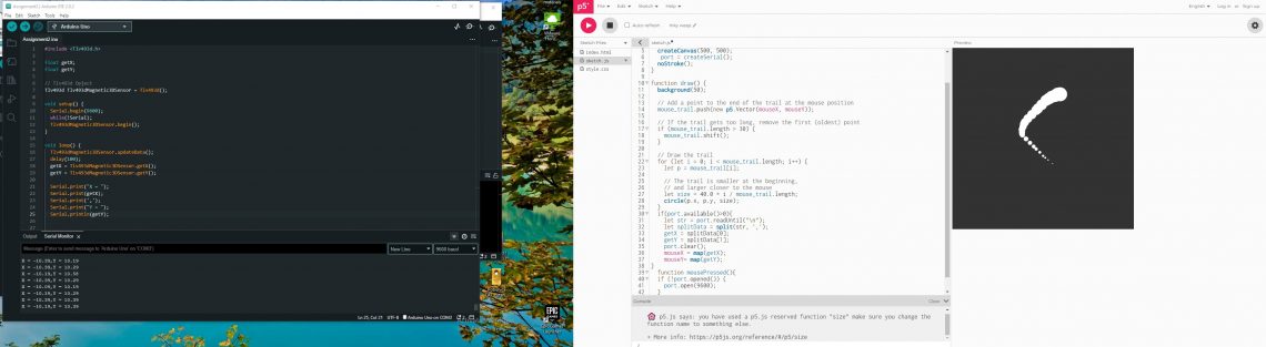
- Reading different sensors with the Teensy and Arduino Nano
- Programming Pure Data patch and connecting with sensor’s values
- Prototyping the installation
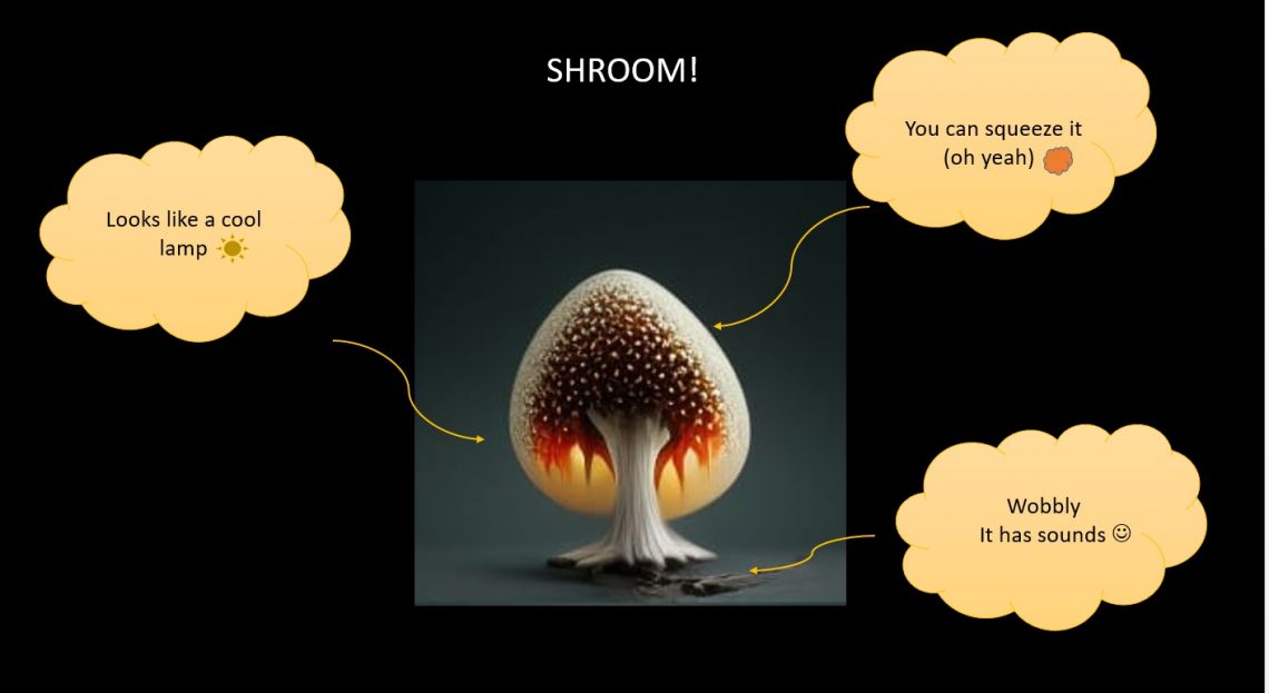
Inspiration for the project came when we saw AI generated picture of mushroom and remined us type of lamps that looks like Super Mario mushroom lamps. We wanted to make something that looks like a lamp but has a different touch texture than normal lamps, and if possible be a sound controller so that by moving or touching we have the ability to change the sound. In addition to that, we also wanted this interactive lamp to have a future purpose as a game controller where the original idea was to use it to control the mushrooms in Super Mario game.
About the process
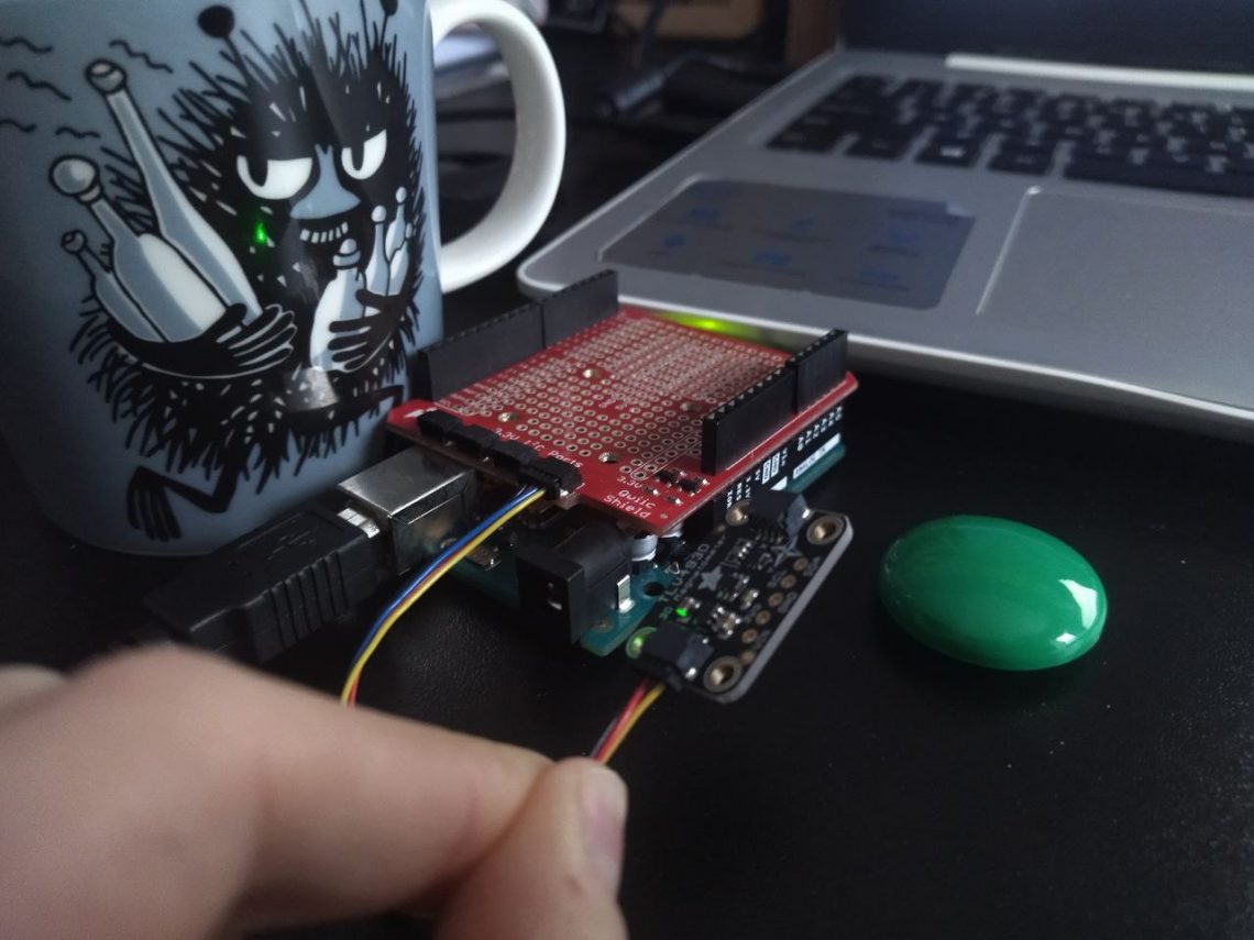
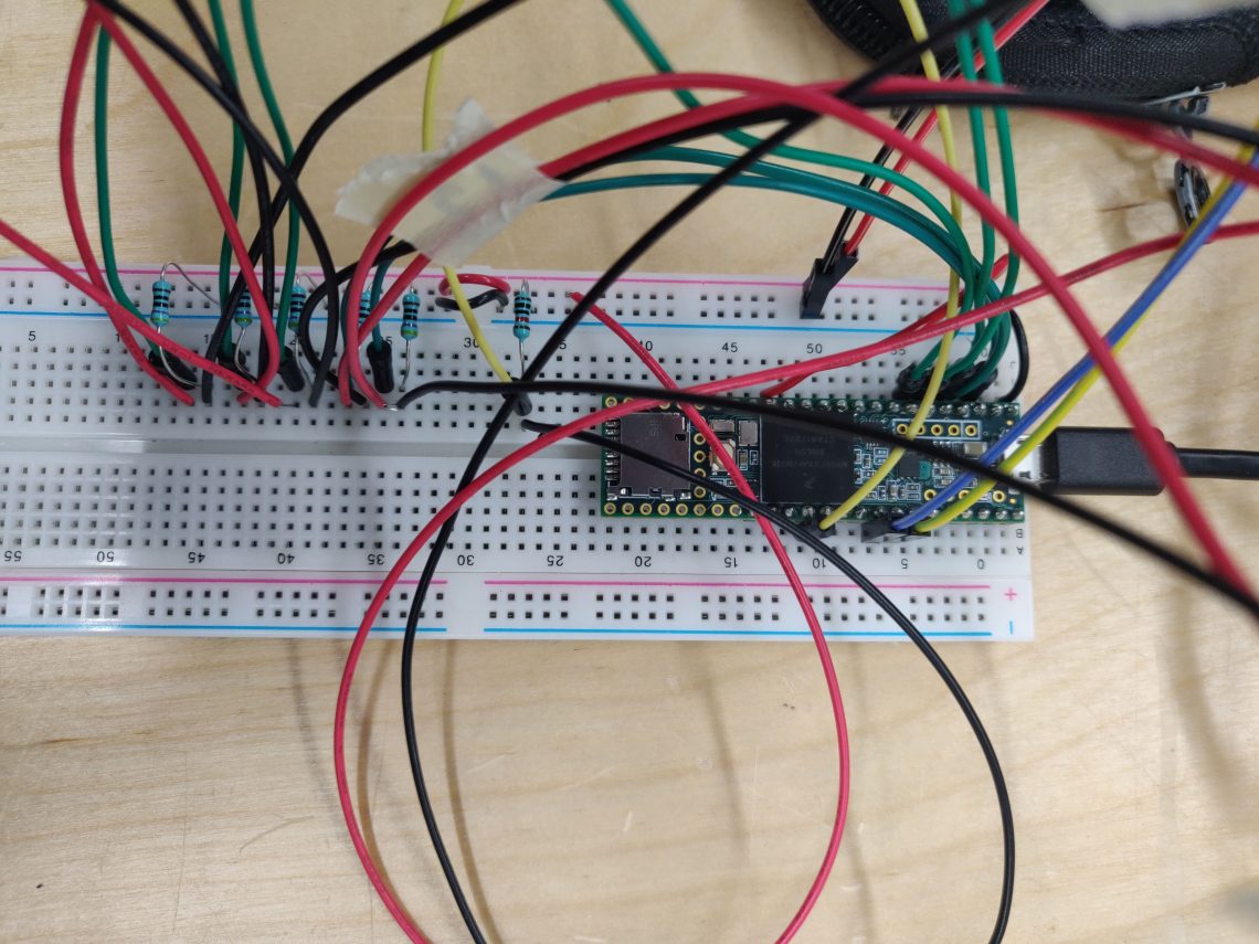
In the first phase of the project, we used Teensy 3.6 (Arduino Nano for testing sensors), two seniors and LED lights. We had to choose the sensor that would work best in terms of the mechanics of the installation itself, which is to get the values detected by the movement so that we can control the sound. The choice fell on the accelerometer. Other sensor that we decide to use to control level of sound as well as LEDs is force sensor.
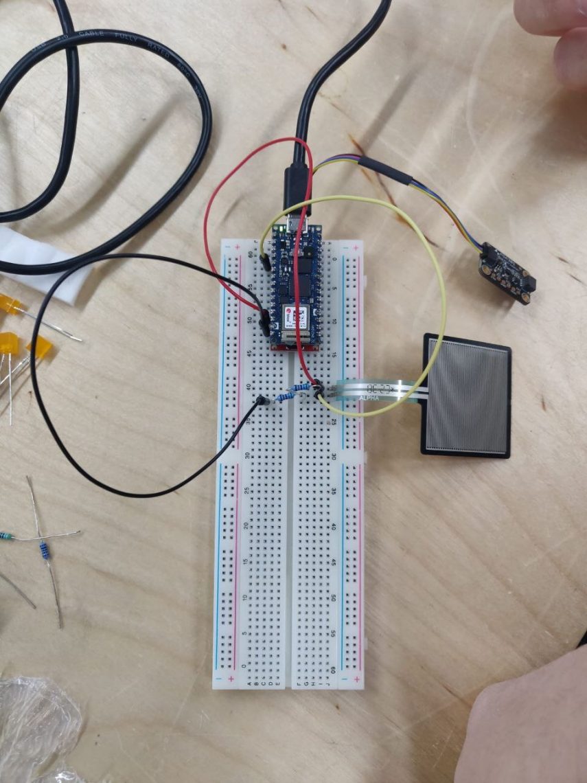
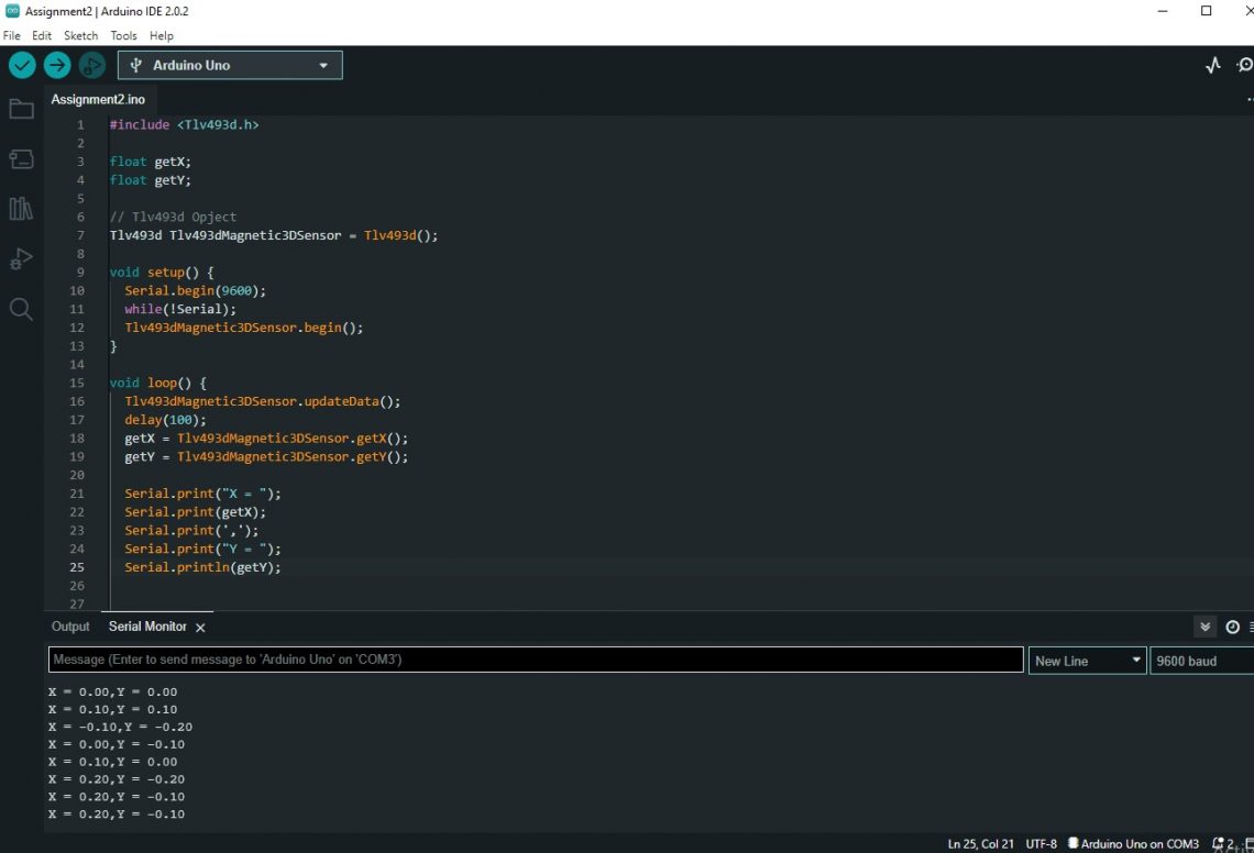
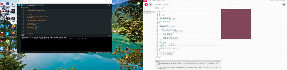
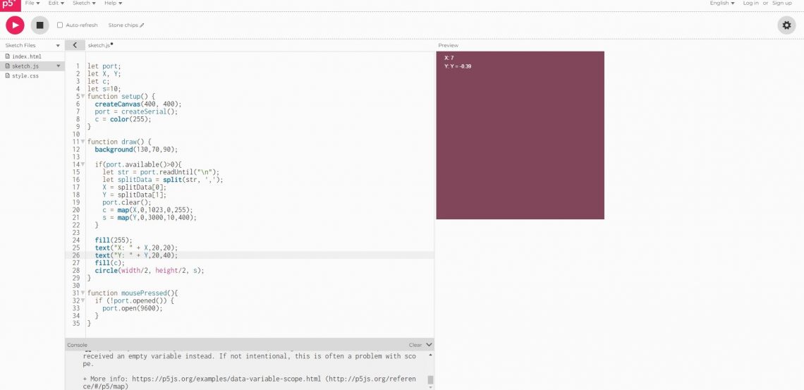
Since that we didn’t previously use Teensy, we decided to test all sensor codes with Arduino Nano. We used the codes that were part of the example that can be found when the sensors are installed in Arduino environment and they worked. In the next steps we tried codes for force sensor and accelerometer with Teensy and to find a way to connect it with Pure Data. The goal was that the values we get from the sensors are registered in Pure Data and that way we have the ability to control sound effects and pitch. To achieve that we used USB midi codes, which gives the ability to send and receive messages. More about that you can find in this page: https://www.pjrc.com/teensy/td_midi.html
The next step was the LED lights which we also tested using the already ready made codes and we wanted to give them the function that when the force sensor is pressed that way they turn on. The stronger the pressure on the sensor, the more the LED lights up, the lower the pressure, the less.
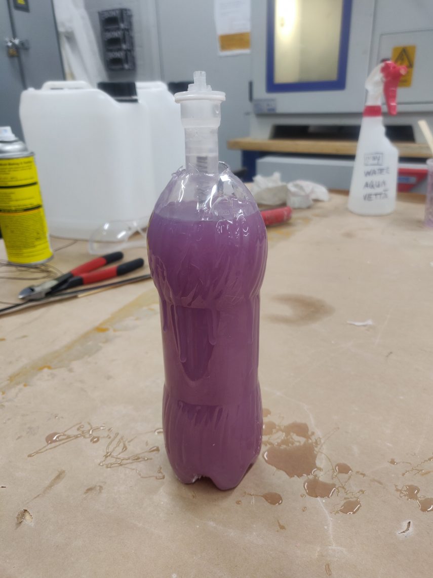
Simultaneously while testing the code, we worked on the prototype of the installation itself. We didn’t realize how much of a challenge it was to make something that had the shape of a mushroom but that it had to look like a lamp and that it took time to choose the materials. The first step was to take what was available, which were bottles of different sizes, one balloons at the end of the silicone used to cover the holes in the windows.
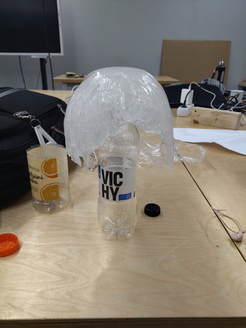
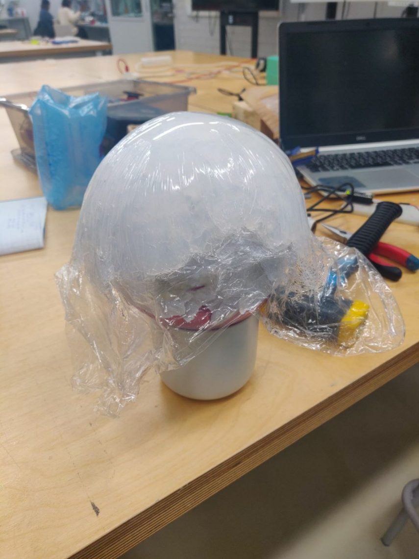
We knew that we wanted the surface itself on the top of the installation to be made of silicone, so I took that type of silicone, poured it into the foil and formed the shape according to the balloon, which I left to dry. The next step was to determine the height of the installation itself, so for that we used the bottles we found in the workshop. After that, we used the bottle as a model to make only the handle of the silicone mushroom. We used a softer type of silicone to make the handle stretchy and moveable, but on the other hand, to be strong enough to return to its original position.
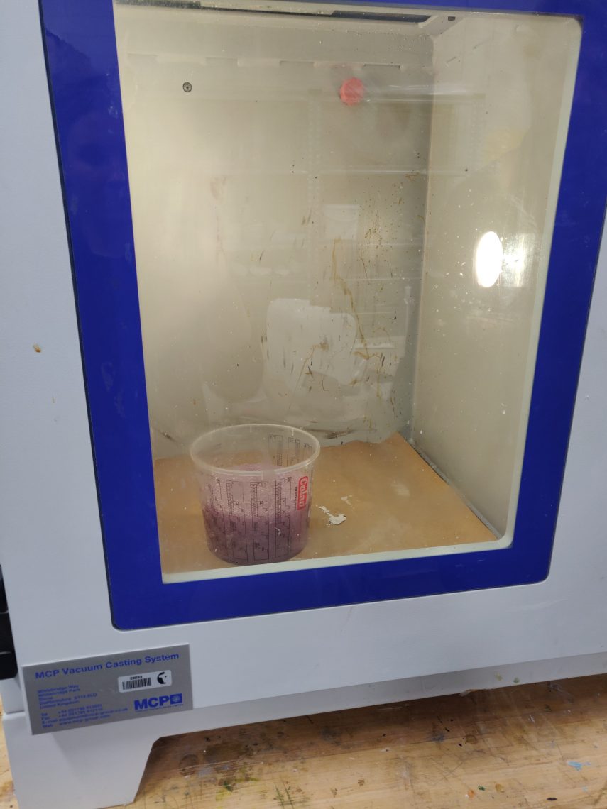
The process of working with silicone looked like we had to pay attention to how to mix both materials that we got in the box, what time and to get out potential air bubbles. We made a hole in the middle of the handle through which we would pass all the electronics.
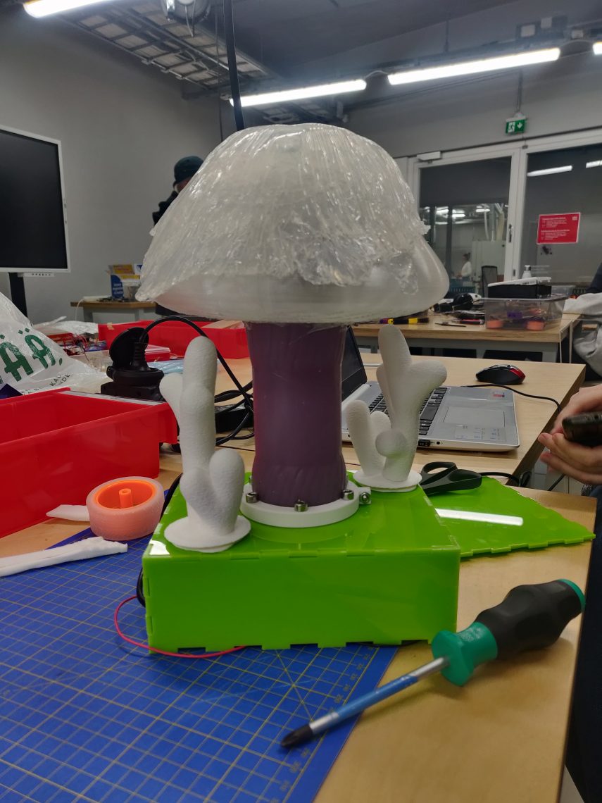
After drying the silicone and a few corrections, we ran all the electronics including the LED lights. The next part was to install the fiber optic cables where the LED lights are so that the light can be spread out as much as possible at the top of the installation.
At the same time, we had to think about what the mushroom cap would look like on which we would place the silicone that we previously modeled on the balloon and we decided to have it 3D modeled and printed on a 3D printer using a transparent material.
To make the whole installation complete, we needed a box that would also be a base for the mushroom. We decided to laser cut the box using green acrylic material. We soldered the entire electronics onto a smaller board that could fit in the box and packed it. The last step was to test all the electronics, to make the changes we wanted in Pure Data in terms of how we want the installation to sound, and to test if it is possible to have three states of Force sensor touch strength.
The final result
Final results of how the installation works looks like this:
- We have programmed the force sensor to have three touch states – weak, medium and strong. Depending on the state in which the sensor is touched, the intensity of the light changes as well as the volume of the sound. the weaker the touch, the weaker the volume and light and vice versa. The sensor is located on top of the installation itself.
- The accelerometer values are read into the Pure data and change the pitch as well as the concentration of the effects to be used. As the installation moves depending on the x and y axis, the sound changes as well.
Video link: https://vimeo.com/782864211
Challenges and learning outcomes:
When approaching something for the first time such as designing an installation like this including coding it, challenges are something that comes up almost regularly:
- Choosing a sensor takes a lot of time. Until we came to the conclusion of using an accelerometer and a force sensor, we tried the joystick and capacitive sensor. Time should be planned to try out different sensors.
- Working with silicone takes a lot of practice. It is very important to take enough time to build prototypes and try things out well in advance. The same goes for 3D printing and making the appropriate model.
- Pure Data is not compatible with any Arduino. Compatibility is possible with Teensy, but it is best to go with Bela board.
- Work with sensors that need to communicate with Pure data should be divided into the following phases: test the sensors individually, see what values they give and what the range is, if necessary, limit or convert the values so that they do not go negative, test the connection via USB midi port with Pure data.
- It’s okay to make mistakes, you learn from mistakes.
Next steps
The next phase of this project is to make the whole installation a joystick with which we will control the game. Sensors will remain more or less the same, perhaps with some added correction. The idea is to link this installation to a Super Mario game clone or make our own game, that’s still under consideration. We will certainly continue to build this project in the coming months, so stay tuned.
To be continued….